QW-Modeller for QuickWave
Free general purpose 3D CAD modeller for QuickWave.
Patch1 for QW-Modeller 2016 for QuickWave
Patch1 for QW-Modeller 2016 includes enhancements in the functionalities of FDTD meshing involving AMIGO (Advanced Mesh Intelligent Generation Option) algorithms, fast and easy FDTD mesh settings and more flexible user interface.
What's new in Patch 1 for QW-Modeller 2016 (released 2016.08.04):
Enhancements:
1. FDTD Mesh: AMIGO meshing taking into account also electric conductivity and magnetic loss of the objects’ materials
2. FDTD Mesh: AMIGO meshing - possibility of changing frequency band of interest
3. FDTD Mesh: maximal accepted cell size step between adjacent cells and automatic cell size step correction in each direction
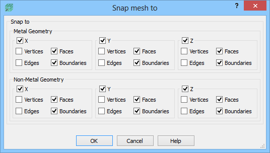
4. FDTD Mesh: new 'Snap mesh to' dialogue for snapping mesh to verices, edges, faces and boundaries separately for metal and non-metal material geometries
5. FDTD Mesh: mesh snap to the specified edge of the Mesh Box
6. FDTD Mesh: indication of minimal cell (red dots) and cells size step (yellow hourglass) in each direction
7. FDTD Mesh: additional information about minimal and maximal cells size in 'Mesh Inspect' dialogue
8. New option in 'Export Option' dialogue for level of details for information displayed in Report View
9. New 'Remove Sections' command (remove all existing sections)
Bug Fixes:
1. QuickWave STUDENT Release not available in QW-Modeller
2. Incorrect shifted Template Port position after export
Mesh Settings dialogue
There are two main options for setting the global meshing: manual and automatic (Amigo). Those options are available in the Maximum Cell Size frame. Manual meshing enforces a user defined cell size along specified axis. Amigo enforces the mesh with a cell size specified by a given Cells per Wavelength ratio. This option takes into account the value of electric permittivity, magnetic permeability, electric conductivity and magnetic loss of the objects’ materials. The user has a possibility of using Manual or Amigo meshing for each direction separately. It can be chosen by checking an appropriate checkboxes in the Manual or Amigo frames. If Manual meshing is checked for a given direction, a cell size needs to be specified. If Amigo option is chosen for a particular axis, the Cells per Wavelength field, which needs to be filled, becomes active. One value of the Cells per Wavelength variable is set for all directions and a corresponding cell size (minimum from all objects’ materials) is displayed next to each axis. Frequency group allows setting the frequency band of interest. The frequency band can be set manually or taken from the project clicking Auto button.
In the Cell Size Step frame the user can introduce maximal accepted cell size step between adjacent cells (indicated on the screen with the yellow hourglass) and activate automatic mesh correction in each direction.
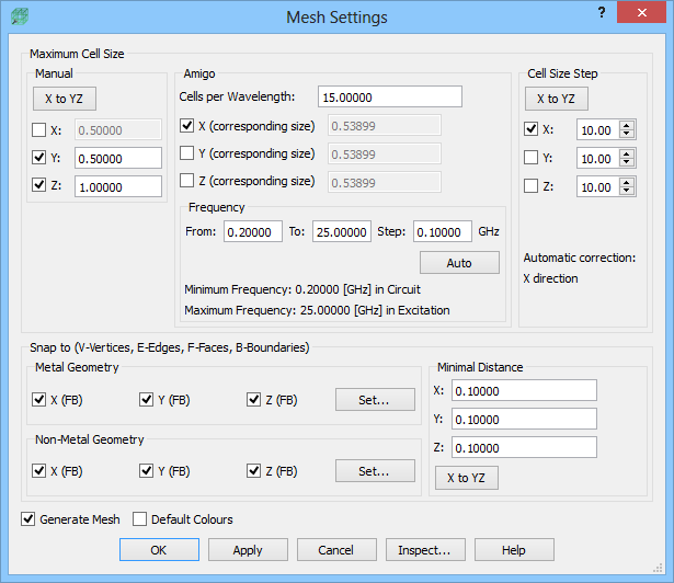
In the Snap To frame the user can activate enforcing additional mesh snapping planes and minimal distance between them. The Metal Geometry and Non-Metal Geometry options allow enforcing mesh snapping planes at all geometry elements (vertices, edges, etc.) for metal and other materials objects, respectively. The Set button invokes Snap mesh to dialogue where the mesh snapping planes can be enforced in each direction separately by checking an appropriate checkboxes.
The Minimal Distance option prevents placing two automatic (resulting from Metal Geometry and Non-Metal Geometry options) mesh snapping planes in a distance smaller than the one specified in a particular direction. This distance condition is not taken into account in case of mesh snapping planes enforced by the user manually, through Snap push button.
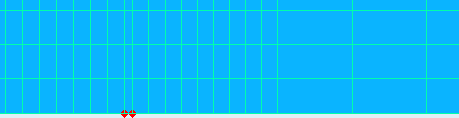
Minimal cell size indicators
Minimal cells in the project are indicated with red dots (separately in each direction). The minimal cell indication appears when the minimal cell size is less than 30% (by default) of the maximal cell size in a given direction.
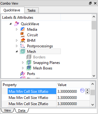
The size factors are assigned to Mesh group and can be changed in the Property Editor.
Cells size step indicators and automatic corrections for cells size step
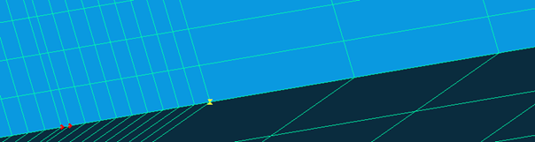
In the Cell Size Step frame of the Mesh Settings dialogue the user can introduce maximal accepted step in cells size between adjacent cells (indicated on the screen with the yellow hourglass) and activate automatic mesh correction in case they appear.
Cell size step indication with the yellow hourglass.
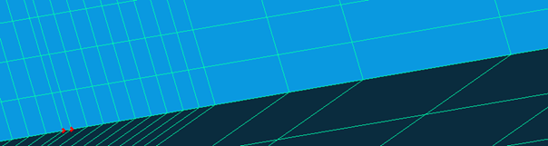
Cell size step reduced with automatic correction.
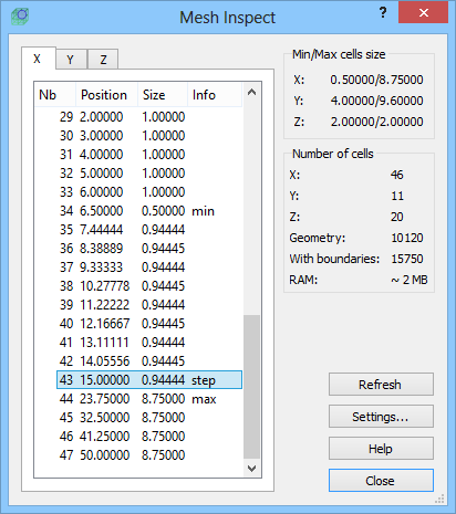
Mesh Inspect dialogue
Mesh Inspect dialogue allows viewing the coordinates of the project’s mesh lines and cells size in each direction. The information contained in this dialogue takes into account the mesh lines resulting from the global meshing and also the mesh snapping planes enforced by the user manually. The information about minimal and maximal cells and about cell size step are also included.
On the right side of the dialogue the information about minimal and maximal cells size, number of cells in each direction and total number of cells in the project can be found. Additionally, the estimation of the size of RAM memory, required for running the simulation, is given.
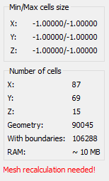
Please note that projects created in the previous versions of QW-Modeller (before Patch1 for QW-Modeller 2016) do not contain information about minimal, maximal cells etc. That is why mesh recalculation is needed.
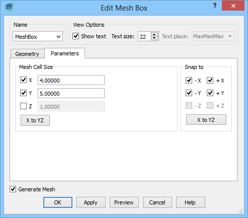
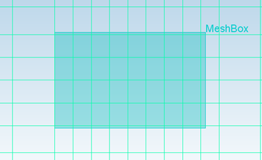
Mesh Box dialogue
Mesh Box is a simple object, which enables setting a specific meshing in the area limited by its size.
The mesh cell size, enforced in the Mesh Cell Size area, can be specified separately for each direction in the X, Y, Z fields. Additionally the user can decide whether the mesh cell size in a chosen direction should be modified according to the given value or the global setting (Mesh Settings dialogue) should be kept. To keep the global setting in a chosen direction, an appropriate checkbox should be unchecked.
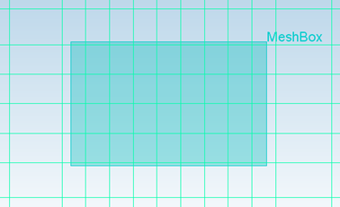
The Snap to area allow snapping mesh to the specified Mesh Box edge.
Snap to -X, +X, -Y, +Y edges.