Field integration in the parallel-plate transmission line
The present example considers contours and paths of integration in the parallel-plate transmission line.
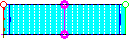
Parallel-plate transmission line with path of field integration.
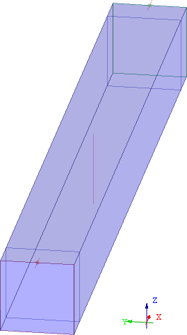
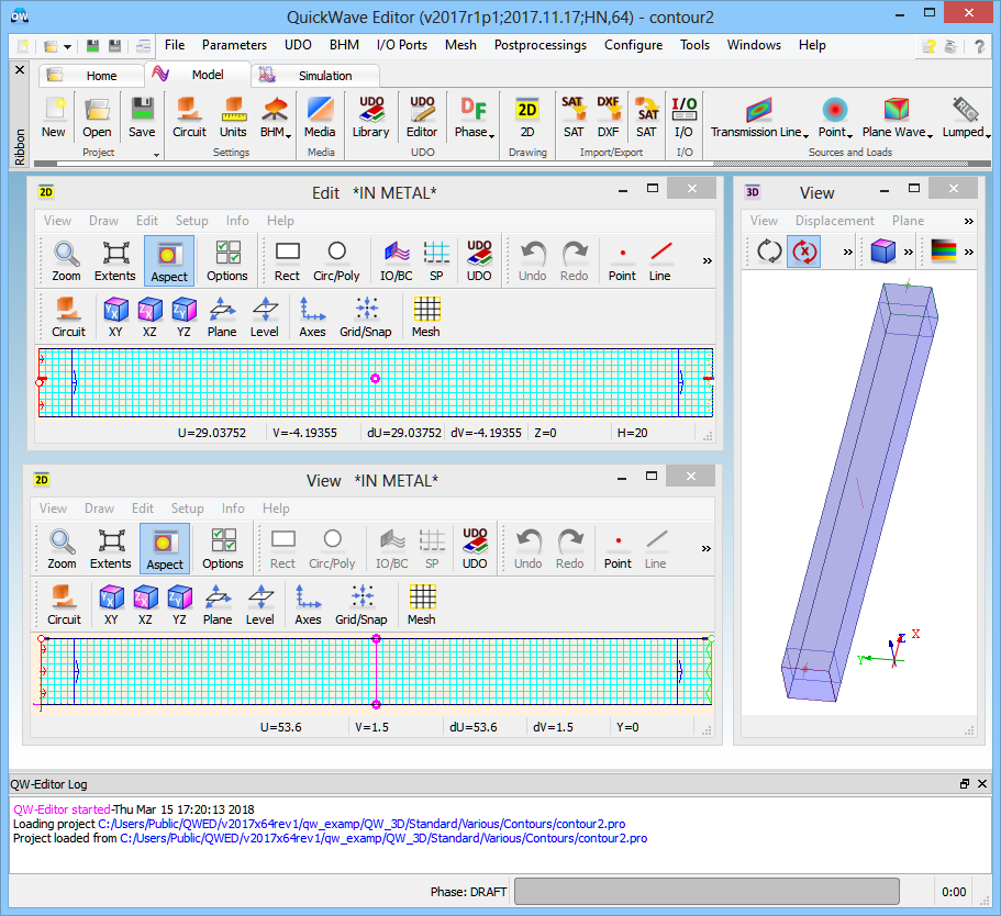
Parallel-plate transmission line with path of field integration project in QW-Modeller.
The parallel-plate transmission line is located along the x-axis and supports a TEM wave with Ez and Hy field components. The path of integration (contoure4 marked in magenta) is defined between two terminal points requested at (50,0,0) and (50,0,10) and effectively snapped to (50,0.5,0) and (50,0.5,10). Hence the integrated field will have the significance of voltage between the two metal plates.
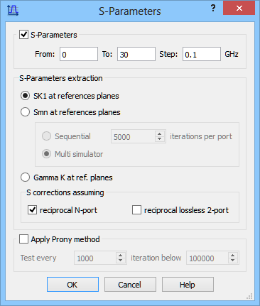
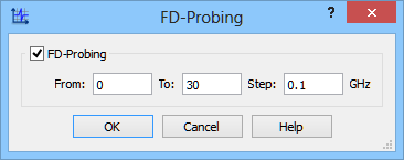
Two types of post-processing will be conducted: S-Parameters (between the two ports) and FD-Probing (of integrated voltage), both between 0 GHz and 30 GHz.
S-Parameters and FD-Probing postprocessings configuration dialogues.
In typical applications of the software setting excitation to the delta pulse is not recommended since it may excite out-of-band resonances that slow down simulation convergence. In this example, the circuit is non-resonant and matched. The delta pulse will excite a wave with (theoretically) frequency-independent available power. With source amplitude set to unity the time-maximum available power is 1W. Since the cross-section of the parallel-plate line is square and the line is filled with air, its characteristic impedance is equal to free-space impedance and voltage amplitude should be (120π)-0.5.
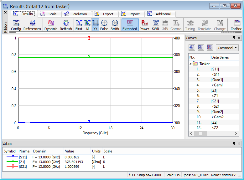
Reflection, transmission and characteristic impedance extracted by S-Parameters post-processing in extended mode. Non dispersive transmission line impedance and good matching is confirmed over the considered frequency range.
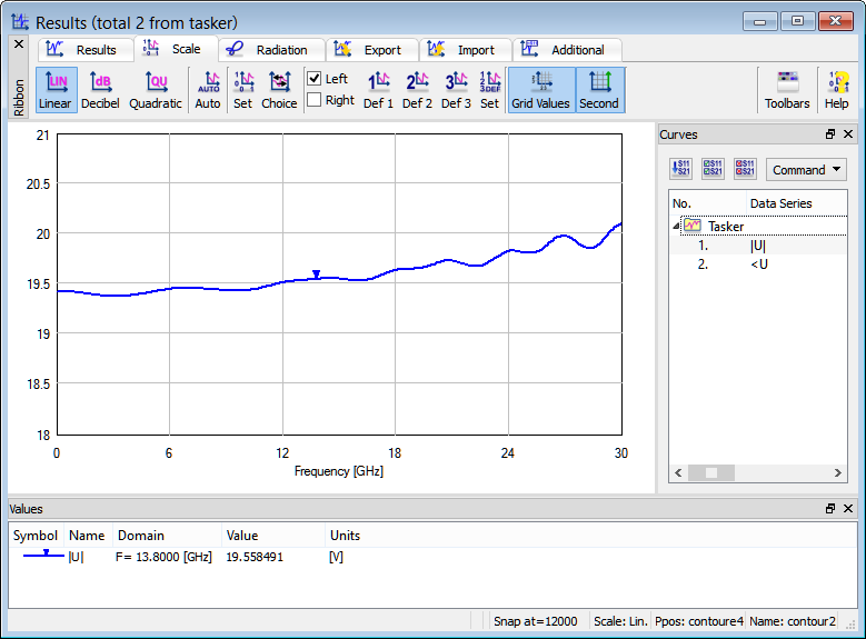
Voltage amplitude extracted by FD-Probing in the contoure4.