FD-Probing (Fourier transform)
QuickWave offers the FD-Probing post-processing that can be invoked for two types of objects and depending on that delivers separate results:
•
for Point Source and Point Probe the FD-Probing post-processing calculates Fourier transforms of the terminal voltage and current, and therefore extracts embedding impedance and admittance
•
for contours the FD-Probing post-processing calculates Fourier transforms of voltage and current along contours and also Fourier transforms of fields integrals along the contours
There are four main applications of the FD-Probing post-processing:
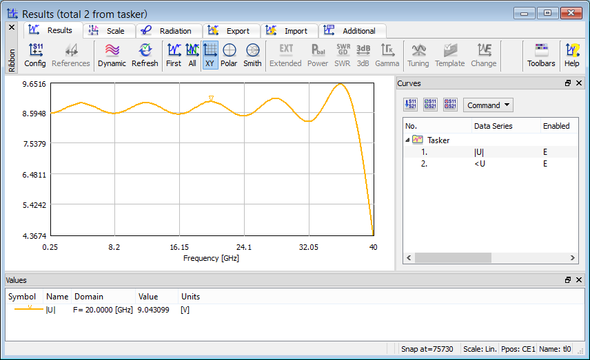
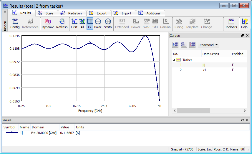
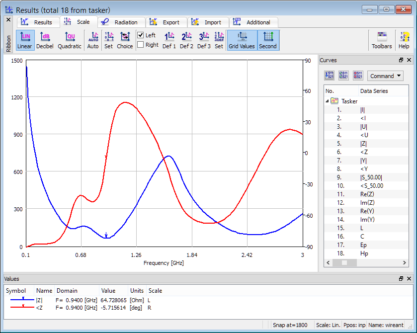
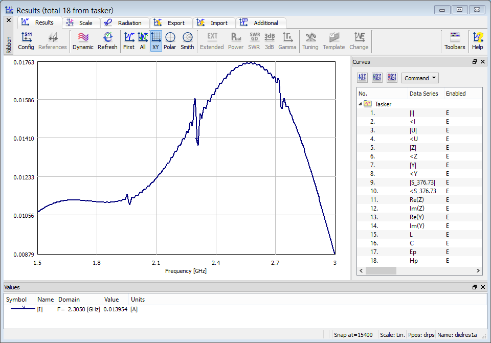
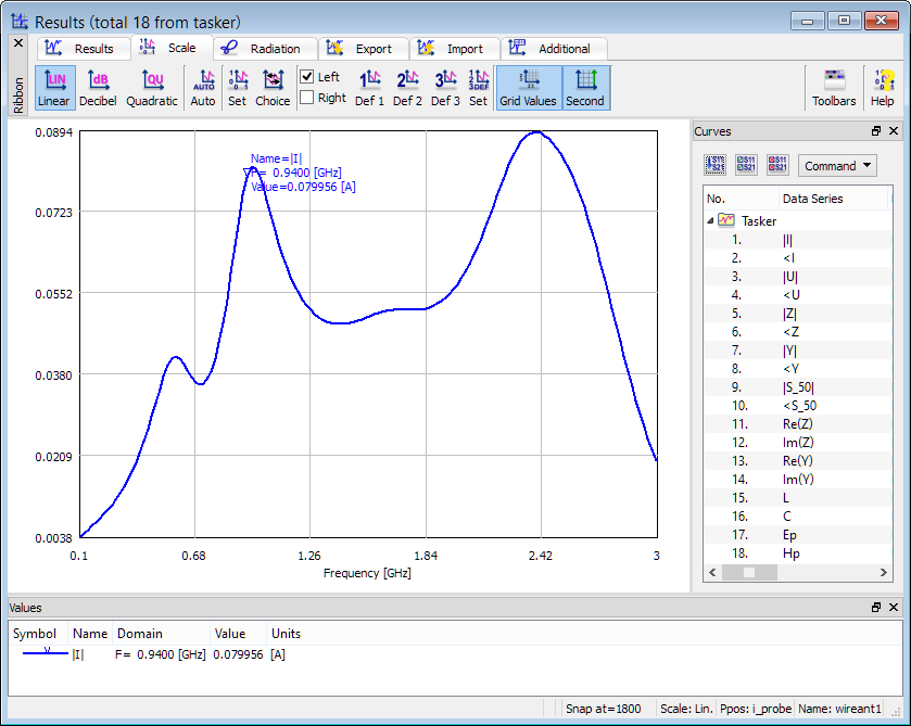
The FD-Probing results contain the following results: Fourier transform of current I through the lumped port and voltage U across the lumped port (amplitudes and phases), absolute value of embedding impedance (Z=U/I), phase of embedding impedance, absolute value of embedding admittance (Y=I/U), phase of embedding admittance, absolute value of reflection coefficient (calculated with respect to the lumped port resistance if its value is finite, and with respect to 50Ω if the resistance is zero or +INF), phase of reflection coefficient, real part of impedance, imaginary part of impedance, real part of admittance, imaginary part of admittance, inductance defined as L=Im(Z)/(2πf), capacitance defined as C=Im(Y)/(2πf), E-field at point Ep, H-field at point Hp.
The FD-Probing results in the case of field integration along an arbitrary path contain the following results:
•
amplitude of voltage and phase of voltage for E-field integration contour
•
amplitude of current and phase of current for H-field integration contour
Analysis of Eigenvalue Problems
FD-Probing post-processing enables analysis of eigenvalue problems (resonant frequencies and field distribution of consecutive modes in arbitrarily-shaped and filled resonators). In this case a point source must be placed inside the resonator. It will serve as auxiliary excitation injecting energy into the structure through finite output impedance. We can watch the results of FD-Probing calculations performed on the current flowing between the source and the resonator in the Results window. With pulse excitation, minima of this current indicate resonant frequencies.
Embedding Impedance for Lumped Elements
FD-Probing post-processing enables analysis of embedding impedance for lumped impedance elements. Typically such an analysis would be performed for lumped impedance elements placed between two metal elements (wires, plates or blocks). The FD-Probing calculations will be performed on the current flowing between the source and the circuit, and on the port voltage.
Currents Induced in Wires
FD-Probing post-processing enables analysis of currents induced in wires. In this case a point probe should be placed on the wire and the exciting field for this point should be selected as the E-field component along the wire, and the point probe impedance should be set to R[Ω]=+INF (the point will in fact act as a probe). The FD-Probing calculations will be performed on the current flowing in the wire (H-field integrated around the point probe).
Field Integration along an arbitrary path
In many practical cases, we may wish to observe integral quantities, such as a line integral of the electric field along a pre-defined integration path. If the field is potential, then this integral has the physical meaning of voltage. Knowing the voltage between two metal objects allows predicting the hazards of arcing and electric breakdown.
The FD-Probing post-processing comes across such needs and enables extraction of currents and voltages by integrating H-fields along a virtual loop surrounding a conductor and E-fields along a virtual line connecting two conductors. At the end, the Fourier transform of these integrals is performed.
This information may be helpful in the analysis of quasi-TEM circuits for verifying the frequency range of their TEM behaviour. Also, lumped element models of parts of 3D structures can be extracted. Please note that for TEM lines, the integration of both electric and magnetic fields over specific contours can be also used for extracting the characteristic impedance of the transmission line, calculated as a ratio of the integration results.