The present example considers a plane wave illumination on a scatterer placed in a free space.
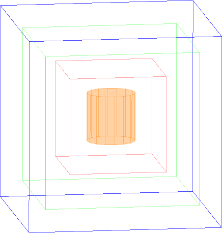
Plane wave illumination with the scatterer.
Simulation model considers a cubic volume of free space (cube side = 40 mm), with absorbing exterior boundaries (marked as blue box), a surface for near-to-far field transformation (NTF box, marked as reen box) with each wall placed 4 mm from an absorbing boundary and a surface for plane wave excitation (plane wave box, marked as red box) with each wall placed 10 mm from an absorbing boundary. The metal cylinder of radius 5 mm and height 10 mm is placed 15 mm above the bottom absorbing wall.
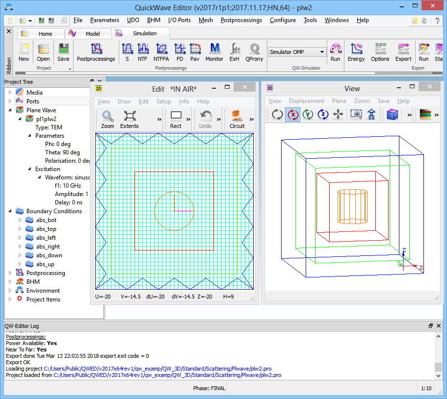
Plane wave illumination with the scatterer project in QW-Editor.
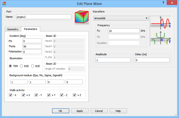
QuickWave enables free space excitation with a plane wave (available as TEM illumination). For this excitation type there are three angles to be chosen: φ (Phi) - azimuthal angle of the direction of wave propagation, θ (Theta) - elevation angle of the direction of wave propagation, Polarisation - polarisation angle of the electric field.
With all these angles set to zero, the incident wave travels along the Z-axis and its electric field vector is oriented along the X-axis. In general, the direction of propagation determines a modified Z' axis, and the electric field orientation determines a modified X' axis, of the modified X'Y'Z' coordinate system obtained from the original XYZ coordinate system by rotation with Euler angles Phi, Theta, Polarisation in the ZYZ Euler convention. For more details about Euler angles refer to Radiation patterns section.
It is advised to refer to Free space incident wave for detailed discussion regarding free space excitation with a plane wave or Gaussian beam.
With the settings of Phi=0 degrees, Theta=90 degrees and Polarisation=0 degrees, the wave propagates in the +X direction and positive E-field is in the –Z direction.
Configuration dialogue of a plane wave box excitation (free space incident wave).
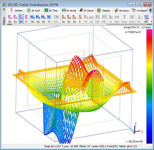
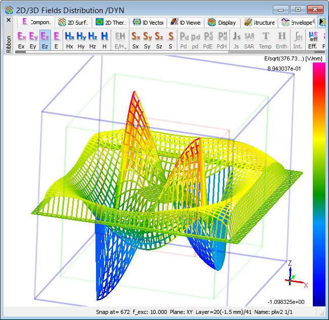
Ez field component of plane wave excitation (Phi=0 degrees, Theta=90 degrees and Polarisation=0 degrees) at 10 GHz.
Time dependent Ez field distribution of plane wave excitation (Phi=0 degrees, Theta=90 degrees and Polarisation=0 degrees) at 10 GHz.
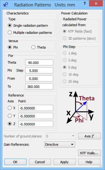
We are interested in calculating the 2D scattering patterns for the considered scenario. The scattering pattern will be calculated versus Phi angle varying between 0 and 360 degrees with a step of 5 degree. They will be calculated with a constant angle Theta equal to 90 degrees. The definition of the angles is explained in the lower right part of the 2D Radiation Patterns configuration dialogue. Note that this definition depends on the choice of the reference axis. The angle Theta is always counted from the reference axis (Z in the considered example). The angle Phi is always counted around it.
2D Radiation Patterns configuration dialogue (used also for scattering pattern configuration).
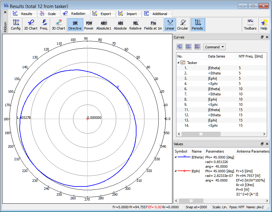
2D scattering patterns calculated at 5 GHz.
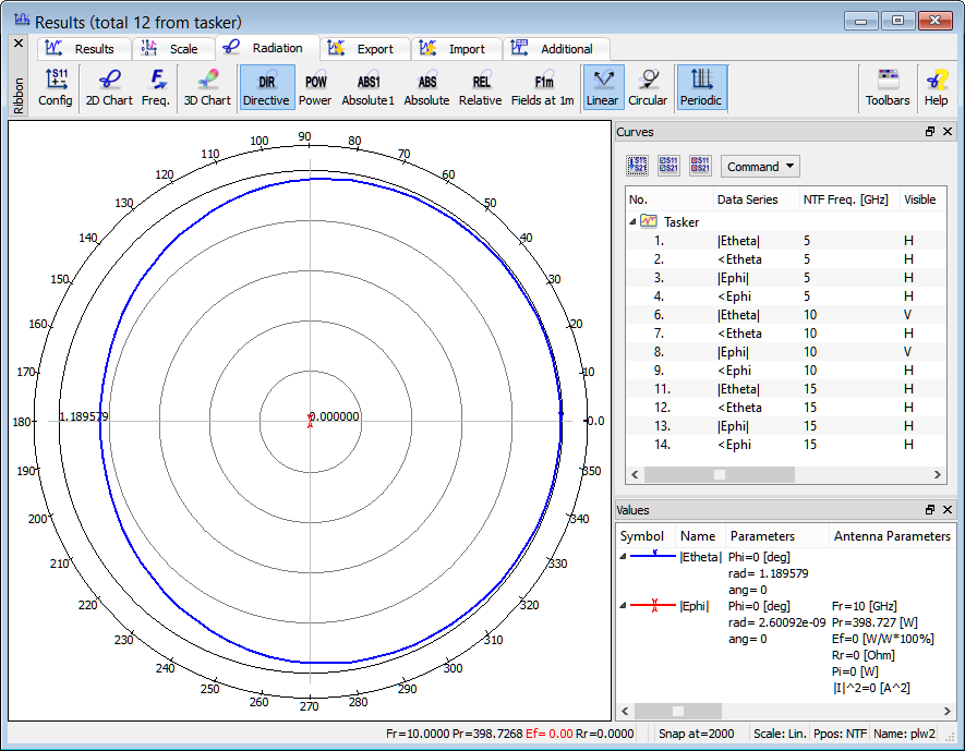
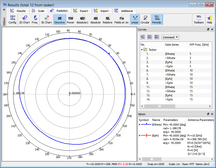
2D scattering patterns calculated at 10 GHz.
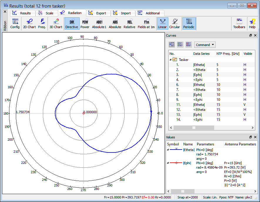
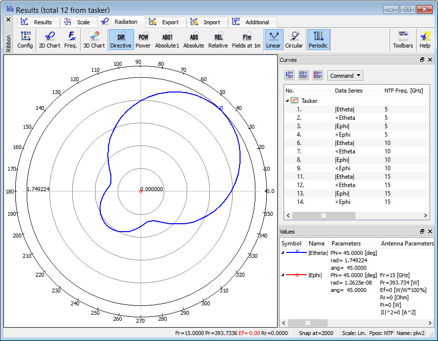
2D scattering patterns calculated at 15 GHz.
Now we change the settings to Phi=45 degrees, Theta=90 degrees and Polarisation=0 degrees.
Configuration dialogue of a plane wave box excitation (free space incident wave).
Ez field component of plane wave excitation (Phi=45 degrees, Theta=90 degrees and Polarisation=0 degrees) at 10 GHz.
Time dependent Ez field distribution of plane wave excitation (Phi=45 degrees, Theta=90 degrees and Polarisation=0 degrees) at 10 GHz.
We are interested in calculating the 2D scattering patterns for the considered scenario. The scattering pattern will be calculated versus Phi angle varying between 0 and 360 degrees with a step of 5 degree. They will be calculated with a constant angle Theta equal to 90 degrees. The definition of the angles is explained in the lower right part of the 2D Radiation Patterns configuration dialogue. Note that this definition depends on the choice of the reference axis. The angle Theta is always counted from the reference axis (Z in the considered example). The angle Phi is always counted around it.
2D Radiation Patterns configuration dialogue (used also for scattering pattern configuration).