| Application |
SPDRs are intended for the measurements of the complex permittivity of laminar dielectric materials including LTCC substrates, but also thin ferroelectric films deposited on low loss dielectric substrates. Additionally, SPDRs can be used for the measurements of the surface resistance and conductivity of various conducting materials such as commercial resistive layers, thin conductive polymer films or high resistivity semiconductors. Such measurements are only possible for large surface resistance samples with Rs > 5 kΩ/square.
|
| Accuracy of measurements of a sample of thickness h |
Δε/ε=±(0.0015 + Δh/h)
Δtanδ=±2*10-5 or ±0.03*tanδ whichever is higher
|
| Operational frequency range |
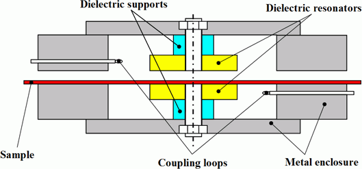
SPDR uses a particular resonant mode. This mode has a particular resonant frequency depending on resonator's dimensions but also, to some extent, on the electrical properties of the measured sample. Thus, each resonator is designed for a particular nominal frequency and the actual measurement is taken at a frequency close to the nominal one. The nominal frequencies of the basic line of SPDRs are: 1.1 GHz, 2.45 GHz, 5 GHz, 10 GHz and 15 GHz. Resonators for the other frequencies in the range between 1.1 and 15 GHz can be manufactured upon special request. |
| Operational temperature range |
-2700C - 1100C |
| Additional equipment needed to perform measurement |
Microwave Q-Meter or
Vector Network Analyser |
| Measurement procedure |
Resonant frequency and Q-factor of the empty resonator and the resonator with investigated sample are measured. Dedicated software is provided for permittivity and dielectric loss tangent determination. The users who have access to one of the PNA/ENA Series network analysers by Agilent Technologies equipped with 85071E Material Measurement software with Option 300 simply upload the QWED's dedicated application into the network analyser and obtain the final results directly on its display.
The users working with different network analysers need to install the software for dielectric properties calculation on a standard PC computer or network analyser if equipped with Windows® operating system.
|
| Additional information |
Minimum size of a sample depends on the operating frequency of the resonator. The minimum sizes of samples for the most popular operating frequencies of the resonators are shown in Table 1a. |