NanoBat
GHz nanoscale electrical and dielectric measurements
of the solid-electrolyte interphase
and applications in the battery manufacturing line
of the solid-electrolyte interphase
and applications in the battery manufacturing line
Quasi-Free-Space measurement with corrugated horn antennas
Download examples (ZIP file).
Note: if the link does not open automatically, press right mouse button, choose “Copy link address” and paste it into a new browser window.
Note: if the link does not open automatically, press right mouse button, choose “Copy link address” and paste it into a new browser window.
Knowledge of dielectric material properties is extremely useful in the design of micro and mm-wave technologies. One of the measurement techniques is the non-resonant free space method. The basic measurement system includes two antennas often terminated with lenses that focus electromagnetic waves. Both antennas are connected to a vector network analyzer. At the center of the system is a sample held by a sample holder. Accurate extraction of complex dielectric properties is largely based on transmission and reflection measurements. As a result, the free-space method seems to be more suitable for medium- and high-loss samples in which both effects will occur. The undoubted advantage of this method is the possibility of broadband measurement. However, additional signal processing is often required due to unwanted reflections and interference.
How to measure the electromagnetic properties of an electrolyte?
The method is mainly adapted to the measurement of solid samples, however, it is possible to adapt the liquid sample to the system under consideration. It must be placed in a sealed container with low permittivity and as low losses. This is important so that it affects the measurement system as little as possible. In this case, there comes another step to the measurement procedure herein, the thickness and dielectric properties of the container must be measured.
Using an axisymmetrical corrugated horn antenna (V2D BOR), a free-space measurement model was created. Thanks to the corrugations, the antenna focuses electromagnetic waves on the sample eliminating the need for lenses. Model is considered in cylindrical coordinates x,ρ,φ under the assumption that the dependence of the fields on the coordinate φ is analytically known. Thus, in reality, we consider the structure in two dimensions x and ρ. In terms of the FDTD grid, we have only one layer of FDTD cells reproducing the shape of the structure in the x, ρ plane. The operating frequency of the antenna is 11 GHz. In the model, the source is excited by a TE11 mode. A LiPF6 + DiMethyl Carbonate electrolyte with a permittivity of 3.1075 F/m and a conductivity of 1.04 S/m was selected as the sample under test (SUT).
A mesh of 151728 cells was applied to the layout along with boundaries. Using 14 MB of RAM, a simulation was run that reached convergence after 27000 iterations lasting 20 seconds.

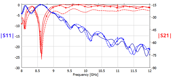
The source was placed on the left side of the system as can be seen from the electric field maximum on the above distribution. The wave passing through the SUT is partially reflected and transmitted, which can be seen from the smaller maxima of the distribution at the right antenna. Certainty is given by the analysis of the scattering matrix parameter plot below. The lossy material (SUT electrolyte) causes a decrease in transmission and an increase in reflection for the operating frequency of the system. Teflon with very low losses has also been placed for comparison.


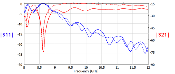
A very interesting advantage of the model is the ability to predict how the system will behave to a change in the concentration of LiPF6 salt in Dimethyl Carbonate solvent. Based on the execution of simulations and appropriate prediction of the potentially created system, it would be possible to extract dielectric parameters and create a valuable characterization of the electrolyte. An example is provided in the scattering matrix parameter plot below.


The NanoBat project has received funding from the European Union's Horizon 2020 research and innovation programme under grant agreement No 861962.
