S-Parameters
S-parameters are calculated in the post-processing called S-Parameters. S-parameters are calculated from Direct Fourier Transforms (DFT) of signals detected at ports using Differential method, which is an original method for S-parameters calculation developed by QWED team (see ref. [9] [44]). It has proven to be accurate, effective, and versatile. It is called "differential" because it extracts the S-parameters from the derivatives of field quantities.
QuickWave allows calculating the S-matrix of an N-port system where N is the number of virtual ports defined in the structure. The system can include both Transmission Line Ports and Point Sources/Probe ports. For each transmission line port, the total fields at its respective reference plane are filtered through the modal template and decomposed into incident and reflected waves via the differential method. Reference impedances for S-parameters extraction are the actual frequency-dependent wave impedances of respective transmission lines.
In QuickWave there are three options for S-parameters extraction:
The S-parameters calculation algorithm is supplemented with the calculation correction options S corrections assuming. When using Smn at reference planes option we obtain the complete information about the circuit, which permits to compensate possible errors due to imperfect matching of the ports. Such complete information is not available when we use the option Sk1 at reference planes. Thus some additional assumptions about the circuit are very helpful in the error compensating procedures. First of all, we use the information about the reciprocity of the structure. Since in principle all the calculated structures are reciprocal the option Reciprocal N-port should always be used. Moreover, if we know that we are considering a lossless reciprocal two-port structure this also can be indicated for the correction algorithm.
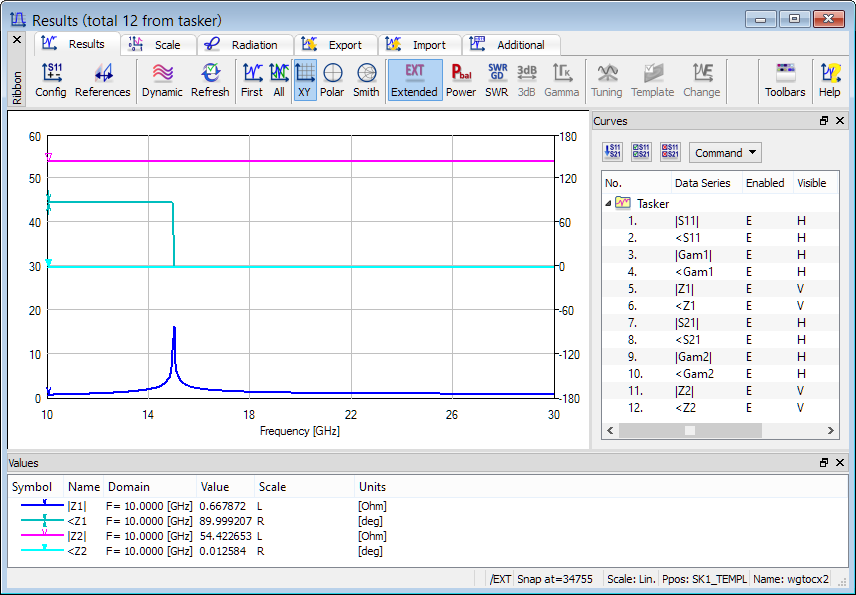
Next to complex S-matrix parameters, S-Parameters post-processing in its standard version delivers also absolute value of the propagation constant. In the Extended Results regime, S-Parameters post-processing calculates also additional information as phase angle of the propagation constant and frequency-dependent complex characteristic impedance of the port lines (which are also reference impedances for the calculated S-matrix).
QuickWave delivers very useful functionality with S-Parameters post-processing, which is a virtual shift of the reference plane. This does not enforce an actual shift of the reference plane (plane of S-parameters extraction), however this newly defined location is taken for S-parameters calculations. Such virtual shift affect phases of S-parameters but also amplitudes in the case of lossy transmission lines or evanescent modes.
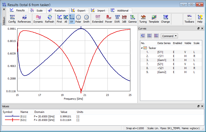
Sk1 at reference planes
In this case we excite the circuit only from port number 1 and calculate the incident (ak) and reflected (bk) waves at each port. This permits to calculate Sk1 = bk/a1.
In the case of i.e. 2 ports, the circuit is excited at the input and only two elements S11 and S21 of the four-element S-matrix will be calculated.
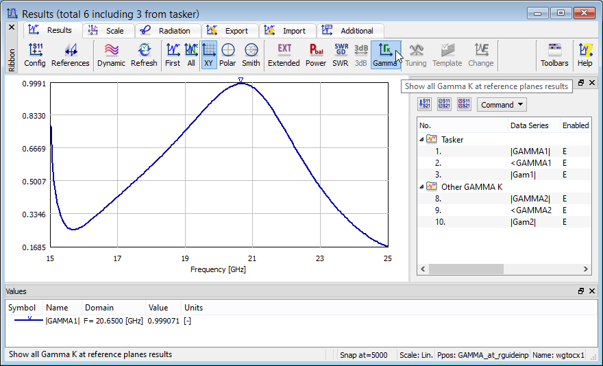
S-parameters results contain three curves per each port. For Port 1 we obtain |S11|, <S11 and |Gam1| results. For Port N we obtain |SN1|, <SN1 and |GamN| results.
|Gam1| … |GamN| denote the absolute values of propagation constants in the transmission lines terminated by consecutive ports.
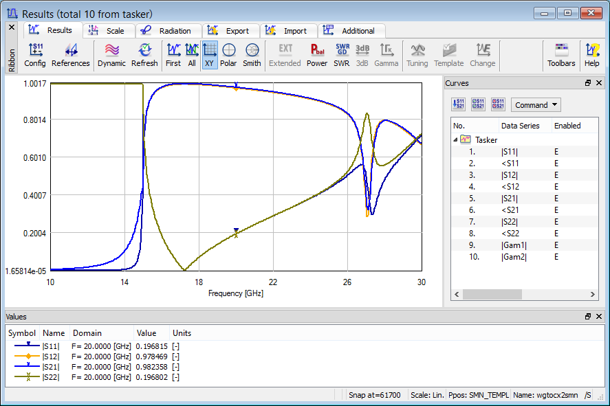
Smn at reference planes - full S Matrix
This is a general case in which we perform N simulations exciting the structure from N different ports, and then compose the complete S-matrix from N sets of partial results. Each of these sets corresponds to excitation from port i when the software calculates the parameters Ski in the same way as the parameters Sk1 are calculated in the Sk1 at reference planes regime. When all N sets are available, the software corrects all the S-matrix elements for imperfect absorbing at all ports (reciprocity is irrelevant at this stage).
The full S-matrix can be computed in two regimes: Sequential regime, in which the software performs N consecutive simulations (with excitation from each of the N ports) and Multisimulator regime, in which the software runs N instances of internal simulator objects in QW-Simulator application, with a different exciting port in each of them.
In the Multisimulator regime, the software runs N instances of internal simulator objects in the QW-Simulator application, with a different exciting port in each of them.
Gamma K at ref. planes - computing reflection coefficients Γ
It allows computing reflection coefficients Γ at several reference planes simultaneously during a single simulation run. It is applicable when a multi-source network is considered, with all the ports operating simultaneously as sources and, consequently, the scattering matrix cannot be computed.
Extended S-Parameters Results
The Extended Results regime allows for calculations of the actual frequency dependent complex wave impedance of transmission lines and the frequency dependent complex propagation constant in the transmission lines.
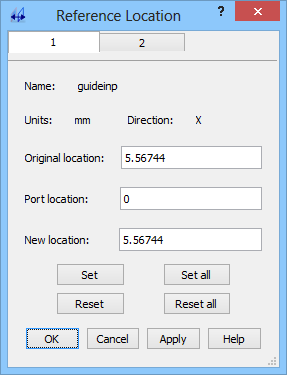
Virtual shift of the reference plane
For each transmission line port, the total fields at its respective reference plane are filtered through the modal template and decomposed into incident and reflected waves via the differential method.
The virtual shift of the reference plane is performed by defining a new location of the reference plane. This does not enforce an actual shift of the reference plane (plane of S-parameters extraction), however this newly defined location is taken for S-parameters calculations. Such virtual shoft affect phases of S-parameters but also amplitudes in the case of lossy transmission lines or evanescent modes. The virtual reference shift option can be used for multiple purposes but becomes especially useful when it is required to calculate the S-parameters at the plane, which corresponds to the port plane or at the discontinuity.
See also: